
Did you ever wonder how we design our parts? Splitters, spoilers and body accessories may look like an easy piece to design but it's much more complicated than you may think. It is obvious that everything starts with a thought in your head. Nevertheless, we must always keep an eye on what is of the most interest on the market. This is why we are only going to cover a few models from the BMW range of cars.

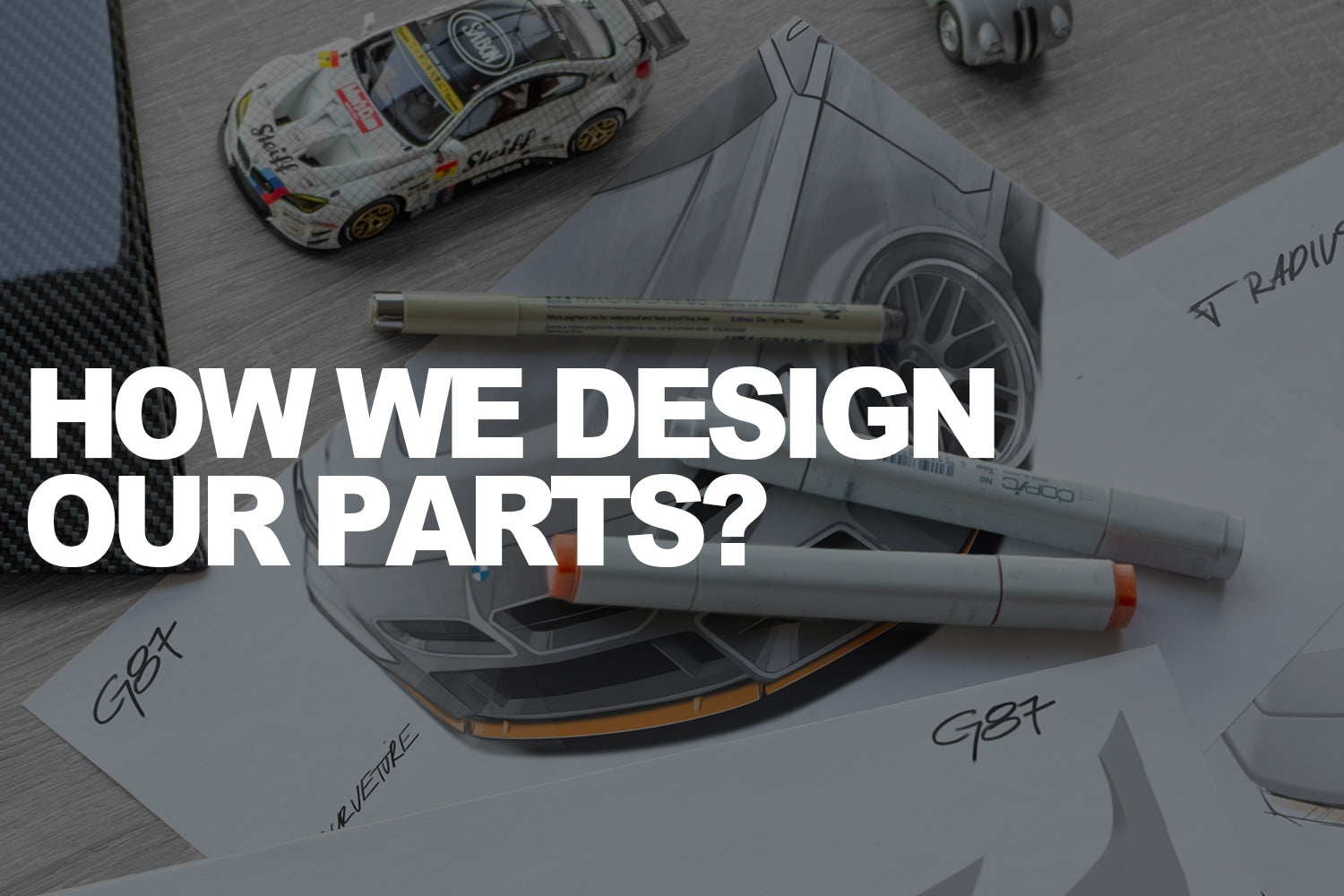
It is Sterckenn's main focus to make sure that its products are of top quality and easy to use. That is the philosophy behind our "OEM+" strategy. Considering how much our clients love their cars, it's crucial that the parts they use don't interfere with their everyday use. We start with sketches and then develop them into high-end 2D renderings in Photoshop by our artists once we have selected the model we want to work on. It's very important to keep the design of the aftermarket part cohesive with the design language of the car. We want our parts to enhance styling and performance. Once the installation is complete, they must represent the right propotions on the car.


In the same time when we are working on the basic styling, a demo car is scanned for reverse engineering purposes. In today's world it is the best solution to design a quality product. What is reverse engineering anyway? This is a process of collecting digital data from the physical model of the car, which represents exact measurements of the surface we need to work on. Scanning takes usually a few hours, depending on the size of the surface we are working on. For most of our projects, we used top of the range GOM software (rebranded to ZEISS inspect in 2023).


Later it is the job of the cad modeler to create the surface of the new part using 2D sketches/renderings and scanned 3D data. The cad modeler and designer will need to understand each other's "design language" for this particular process to work. The more they are connected, the faster the work goes. It's usually a work of compromise between the two. The sketch of an artist does not always show the real shape and surface of the product, especially at an early stage of the design process. However, it gives a strong impression of the final result we want to achieve. It is the stage where art clashes with mathematics. A lot of issues have to be taken under consideration. Part has to fit well but also use existing genuine OEM mounting points. This solution reduces the number of screws used for installation and has to be applied at the earliest stage of 3D design. For example Sterckenn doesn't use double-sided adhesive tape for mounting splitters. M-Power vehicles are achieving very high speeds and tape is simply not good enough for our standards.

 When the 3D model is considered ready certain analyses like CFD or FEM are applied. CFD is a computer-aided design (CAD) technique that utilizes simulation and analysis to calculate the behavior of liquids or gases in and around the vicinity of a product. When the design of the model is locked, the cad modeler cleans up the 3D model to a class-A standard. Class-A is the highest surface quality level, and it demands a high level of automotive design knowledge as well as surface modelling skills. It is a very important stage for future manufacturing procedures. It is now possible to create a 1:1 scale model of the product from this point forward. A high density polyurethane board is modeled by a CNC machine to create the prototype. We use it to check proportions, fitment and surface quality before entering production. We will publish a separate post about the manufacturing process later this year. Stay tuned!